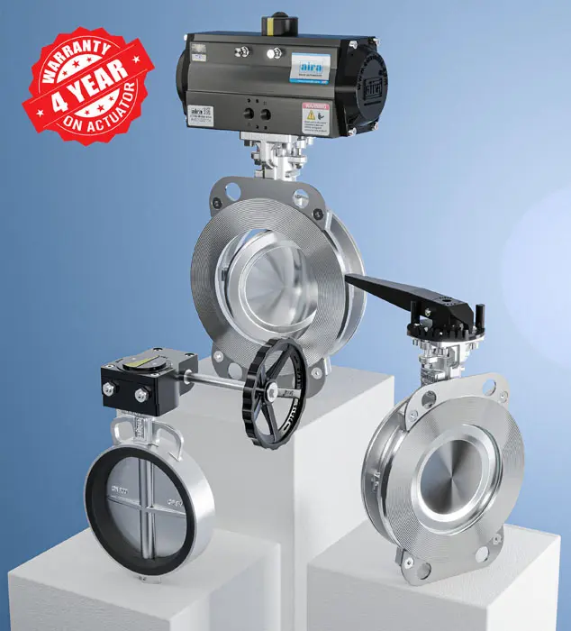
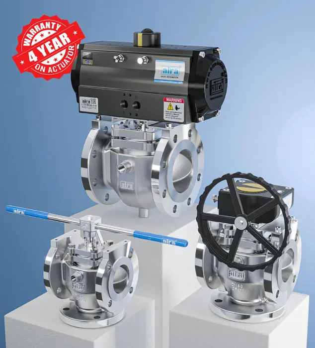
If you’re evaluating a pneumatic drum type control valve for a process line, you probably already know what it does — precisely regulate flow using a rotating drum and a pneumatic actuator. What’s harder to find is a clear technical breakdown of how it actually works, how it stacks up against other control valve types, and how to keep it running without unplanned downtime. That’s what this guide covers.
1. Anatomy of a Pneumatic Drum Control Valve
Before understanding the working principle, it helps to know what’s actually inside the valve body:
- Drum (rotor): A cylindrical element with a precisely machined port profile. Its rotation angle determines the effective flow area.
- Valve body: Houses the drum and defines the flow path. Typically cast in stainless steel, cast iron, or ductile iron depending on the process medium.
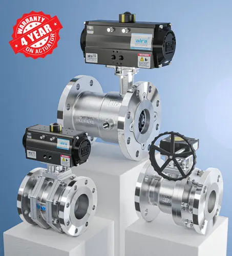
- Pneumatic actuator: Converts compressed air pressure into rotary torque. Most drum valves use a rack-and-pinion or scotch-yoke actuator for a 90° quarter-turn motion.
- Positioner: Translates a 4-20mA or pneumatic control signal into a precise actuator position, allowing modulating (not just on/off) control.
- Seals and bearings: Maintain a pressure-tight seal between the drum and body while allowing low-friction rotation. Seal material (PTFE, Viton, EPDM) is chosen based on chemical compatibility and temperature.
- Limit switches / feedback sensors (optional): Provide position feedback to the control system for closed-loop operation.
The interaction between drum profile design and actuator torque is what gives this valve type its characteristic flow control curve — which is the next thing worth understanding.
2. Working Principle — A Technical Breakdown
A drum control valve doesn’t just open and shut a flow path — the shape of the drum port is engineered to produce a specific relationship between rotation angle and flow rate (its flow characteristic).
Step-by-step signal-to-flow sequence:
- The control system sends a signal (typically 4-20mA or 3-15 psi pneumatic) to the positioner based on the desired flow setpoint.
- The positioner meters instrument air to the actuator, generating rotary torque proportional to the signal.
- The actuator rotates the drum through a precise angle — this is where drum valves differ from simple butterfly valves, because the port geometry is designed for a specific Cv (flow coefficient) vs. rotation angle curve, often linear or equal-percentage rather than the quick-opening curve typical of a basic damper-style valve.
- As the drum rotates, the overlap between the drum port and the body port changes, altering the effective flow area and therefore the flow rate.
- Position feedback (via limit switch or smart positioner) is sent back to the control system, closing the loop for accurate, repeatable control — critical in processes where +/-1% flow accuracy matters.
Readers also like to read: How to Choose The Best Valve Manufacturer
Why this matters in practice: Because the drum’s port geometry (not just its open/close position) governs the flow curve, drum valves can be specified with a flow characteristic matched to the process — something a simple on/off valve can’t offer. This is the key technical differentiator worth understanding before you compare it to alternatives.
3. Drum Valve vs. Other Control Valves: When to Choose Which
| Parameter | Drum Control Valve | Butterfly Control Valve | Globe Control Valve | Ball Control Valve |
|---|---|---|---|---|
| Flow characteristic control | Engineered port profile — linear/equal % | Mostly quick-opening | Excellent — best for precise throttling | Good, segmented ball improves control |
| Torque required | Moderate | Low | High (especially at high pressure drop) | Moderate |
| Space/footprint | Compact, wafer-style | Compact | Bulky (in-line, heavier body) | Compact |
| Pressure drop handling | Good for moderate ΔP | Limited at high ΔP | Best for high ΔP applications | Good |
| Typical use case | Slurries, powders, granular/bulk solids, moderate-pressure fluid control | Large-diameter, low-pressure on/off or basic throttling | High-precision throttling in clean fluid/steam service | General-purpose modulating control |
| Maintenance access | Moderate (seal replacement needs partial disassembly) | Easy | More complex (packing, seat wear) | Easy |
Rule of thumb:
- Choose a drum valve when you’re handling bulk solids, powders, or slurries where a full-bore, low-turbulence flow path matters, or where you need a specific engineered flow curve in a compact footprint.
- Choose a globe valve when throttling precision is the top priority and space/cost are secondary.
- Choose a butterfly valve when the requirement is mostly on/off or coarse throttling on large pipe diameters.
- Choose a ball valve for general-purpose modulating service where tight shutoff is also required.
4. Sizing & Selection Considerations
A few technical factors that determine correct selection (beyond just matching pipe size):
- Cv requirement: Calculate required flow coefficient based on maximum flow rate and allowable pressure drop — undersizing causes excessive velocity/erosion, oversizing causes poor control resolution at low flow.
- Actuator torque margin: Always size the pneumatic actuator with at least 25-30% torque margin above the calculated breakaway and running torque, especially for abrasive or high-viscosity media.
- Seal material compatibility: Cross-check seal material against the process medium’s chemical compatibility and temperature range — this is the most common cause of premature failure.
- Fail-safe requirement: Decide whether the application needs fail-open, fail-close, or fail-in-place on loss of air supply, and specify the actuator/spring configuration accordingly.
- Certification needs: For boiler or pressure-vessel applications, confirm IBR (Indian Boiler Regulations) approval is required and specified at the ordering stage.
5. Maintenance Best Practices & Schedule
| Frequency | Task |
|---|---|
| Weekly | Visual check for air leaks at actuator fittings and tubing |
| Monthly | Verify positioner calibration against setpoint signal |
| Quarterly | Inspect drum seals for wear, hardening, or chemical attack |
| Quarterly | Check actuator mounting bolts and coupling alignment for looseness |
| Annually | Full drum and seal inspection; replace seals proactively in abrasive/slurry service |
| Annually | Test fail-safe action (loss of air simulation) |
Good practice tips:
- Keep instrument air supply filtered and dry — moisture in the air line is a leading cause of positioner and actuator faults.
- Log actuator response time at each inspection — a gradually increasing response time often signals early seal or bearing wear before it becomes a failure.
- Avoid over-tightening packing/seals during reassembly — this increases torque demand and accelerates actuator wear.
6. Common Problems and Troubleshooting
| Symptom | Likely Cause | Fix |
|---|---|---|
| Valve doesn’t reach full open/close | Torque insufficient / actuator undersized | Re-verify torque calculation, check air supply pressure |
| Erratic flow control | Positioner calibration drift | Recalibrate positioner against control signal |
| Leakage past the seat | Worn or chemically degraded seal | Replace seal with correct material grade |
| Slow actuator response | Air supply moisture/contamination, or clogged filter-regulator | Clean/replace air filter-regulator, check air line condition |
| Excessive drum wear/erosion | Valve undersized for velocity, or abrasive media | Re-check Cv sizing, consider hardened trim material |
Looking for a drum valve for your application? Check specifications, sizes, and materials on our pneumatic drum valve range.
7. FAQs
Q: Is a pneumatic drum control valve the same as a rotary valve? A: They’re related but not identical — a drum control valve is a specific type of rotary valve designed with an engineered port profile for modulating flow control, whereas “rotary valve” is a broader category that also includes simple on/off rotary designs.
Q: Can a drum valve be used for isolation (fully on/off) duty, not just control? A: Yes, most drum valves can perform tight shutoff, but if isolation is the only requirement, a simpler and more cost-effective valve type may be more appropriate — drum valves earn their cost premium in modulating service.
Q: What does IBR approval mean for a drum valve? A: IBR (Indian Boiler Regulations) approval confirms the valve has been tested and certified for use in boiler and pressure-vessel applications per Indian statutory requirements — relevant mainly for steam and high-pressure service.
Q: How often should drum valve seals be replaced? A: This depends on the media — clean fluid service may go 2-3 years between seal replacements, while abrasive slurry or powder service may require annual replacement. Condition-based inspection (per the schedule above) is more reliable than a fixed interval.
Q: What’s the difference between the actuator’s torque rating and the valve’s actual torque requirement? A: The actuator’s torque rating is its maximum output; the valve’s actual requirement (breakaway + running torque) should never exceed about 70-75% of that rating, preserving margin for wear, temperature effects, and media viscosity changes over the valve’s service life.